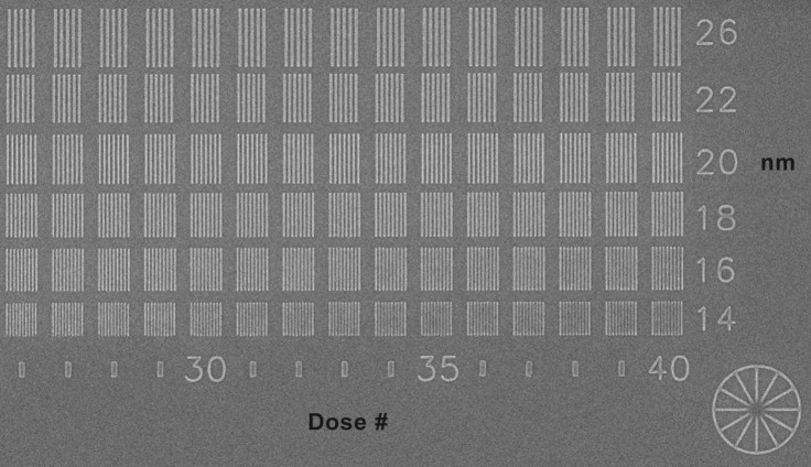
Careful measurements of the linewidths show that the groups in the bottom row range from 14.1 nm (group #26) to 16.2 nm (group #36). The top row ranges from 24.7 nm (group #26) to 26.7 nm (group #36). The groups with doses above #36 are increasingly over exposed.
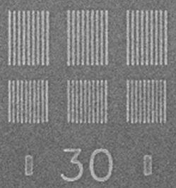
The smaller image shows an enlarged view of the doses near #30 which produced lines in the bottom row that are ~15 nm wide with ~13 nm spaces.
The imaging was done after development without any metallization. The resist is a proprietary resist on a silicon substrate.
This work was done by Inpria Corporation using NPGS at the University of Oregon.
Tips: When initially exposing a dose matrix, the goal is to obtain features that clearly range from `too low' to `too high' as shown in the images above. Subsequent exposures may be performed that target a smaller range that includes the ideal dose. Also, when the test features are all aligned in one direction, as in the case of these vertical lines, including the diagnostic wheel structure is very useful in order to confirm that the astigmatism in the beam was well optimized during the exposure.